When two vehicles charge more slowly together, record the conditions before deciding that a charger is faulty. The equipment may be sharing a total power allowance, the site may be limiting supply, or one or both vehicles may be requesting less power. A useful incident record separates those possibilities.
Start with the time the second session began and the change observed at each output. A screenshot of two low power readings shows an outcome, but it does not explain which limit produced it.
Separate four different power limits
For DC fast charging, identify the total output available to the active sessions. Then record each outlet and cable limit, the site's available electrical supply and each vehicle's acceptance under the current conditions. On an AC installation, include each vehicle's onboard charger limit and the allocation across the relevant charge points. Keep these boundaries separate even when every display uses kW.
The cable's current rating and operating voltage matter alongside any stated power rating. Vehicle state of charge, battery condition and charging control can also affect requested power. The US Alternative Fuels Data Center notes that charging time depends on vehicle, battery, equipment and supply conditions; equipment nameplate power alone does not establish the observed session rate.
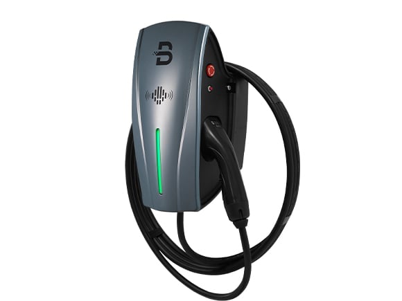
BENY's public DC and AC charger range includes a BXDC listing that describes dynamic power sharing. For an installed DC unit, obtain its own allocation rules and output limits; one product's description does not define another model's behaviour.
Ask how the equipment allocates power
If outputs share power, ask for the documented allocation logic. It may depend on active sessions, available modules, vehicle requests or a configured priority. Do not assume that two connected vehicles always receive an equal split.
Power sharing is also not exclusive to a split-cabinet layout. Equipment configuration and control functions determine the behaviour; the visual arrangement alone does not explain the allocation. Where a supplier describes a dynamic DC power matrix or allocation algorithm, request its operating boundaries in terms that can be checked on site.
Record any relevant settings and software version. An operator should be able to distinguish the intended configuration from a changed setting or an unavailable part of the power system.
Capture a timeline, not isolated readings
Record each session identifier, physical output and vehicle, along with start times and the available state-of-charge information. Preserve readings before and after the second vehicle connects. Include site power or controller records if the responsible team can export them at a comparable interval.
Consider a purely illustrative installation with 180 kW available across two outputs. If one vehicle can accept 100 kW and the other requests 50 kW, a total of 150 kW does not by itself prove a 30 kW equipment fault. There may be no vehicle request for the remaining capacity. This example does not describe a particular charger's allocation rules.
The same discipline applies when a total drops after a building load increases. Without a timeline connecting the site limit and charging records, that relationship remains a possibility rather than a demonstrated cause.
Note thermal and vehicle conditions
Record relevant displayed temperature warnings, derating indications and environmental conditions. Distinguish cable cooling from power-module cooling when asking the service team what may have limited operation. They concern different parts of the system.
Use the manufacturer's documented derating information for the installed configuration. A hot day does not, by itself, prove thermal derating, and a cooled cable does not establish that the power modules can sustain full output in every condition.
Avoid changing vehicle targets, controller limits or equipment settings simply to chase a higher number. Preserve the original evidence and agree any diagnostic test with the responsible operator and service team.
Request a test that separates the causes
Ask the service team for a controlled comparison with known equipment settings and suitable vehicles. State which question the test will answer: output allocation, a site restriction, vehicle acceptance or an equipment limitation.
Keep the final record tied to the tested conditions. It should show the applicable limit, the evidence supporting that conclusion and any unresolved factor. That gives the operator a more useful answer than a blanket statement that two vehicles charging together must be slow or that the charger must be defective.